
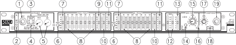
Click on a number for more information
- Acoustic INSTRUMENT INPUT: is a stereo 1/4"" TRS (Tip-Ring-Sleeve) INPUT jack for use with any acoustic instrument with two pickups; however, also accepts instruments with only one pickup. When using a mono cable, signal is routed to the TIP selected by the Input Wiring Switch.
- MIC & PIEZO pickup input OVERLOAD indicators: An individual red indicator for each type of pickup. Useful in monitoring pickup level and initially in setting PICKUP GAIN TRIM controls. These indicators light approximately 4 dB before actual clipping, so occassional flickering is okay, but they should never be allowed to light steadily.
- PHANTOM POWER indicators: are either Off=no Phantom Power; Yellow=+15 VDC Phantom Power; or Green=+6 VDC Phantom Power.
- Input wiring switch: allows choice of Input wiring. Either TIP=PIEZO and RING=MIC, or vice-versa. Proper setup requires careful selection—if in doubt, consult the technician that wired your instrument for the correct choice.
- Input PICKUP GAIN TRIMS: set the proper Gain for each pickup. Range is from 6 dB minimum to 60 dB maximum.
- PICKUP INVERT switches: Invert the polarity (phase) of the piezo pickup with respect to the mic pickup. Either MIC or PIEZO PICKUPS may be individually Inverted.
- LOW CUT frequency: adjusts the corner frequency of the LOW CUT (high-pass) filter from 15 Hz to 250 Hz. Use to reduce unwanted low frequencies in either MIC or PIEZO PICKUPS.
- 7-band graphic equalizer boost/cut controls: Seven sliders that control the amount of boost/cut for each of the indicated bands in both MIC and PIEZO sections. A grounded center detent guarantees flat response for filters not used.
- PIEZO PICKUP output LEVEL: adjusts the Level of the PIEZO OUTPUT jack. Located post-LEVEL and pre-PAN, so it is dependent on the position of the PIEZO PICKUP LEVEL control and independent of the PIEZO PAN control.
- PAN control: Separate controls for both PIEZO and MIC PICKUP sections allow routing the signal anywhere from A-only to B-only at the Main Output.
- LEVEL controls: Separate PIEZO and MIC LEVEL controls the overall Level of each signal.
- SEND A/B controls: adjust the amount of signal at each of the SEND jacks.
- RETURN control: is a “stereo” Return. Controls the amount of A and B entering the RETURN jacks.
- MAIN OUT MUTE button: Mutes both A and B Main Outputs. Does not affect the Headphone Output. The red LED indicates a Muted output.
- MAIN OUT A & B LEVELS: Concentric controls used to separately set the Main A & B Output Levels.
- MAIN OUT OVERLOAD indicator: monitors both A and B Main Outputs. An overload condition (within 4dB of clipping) on either Channel causes this red LED to light.
- HEADPHONE LEVEL: controls the volume of the HEADPHONE Output jack.
- POWER indicator: glows yellow when the proper power supply is connected and powered.
- Headphone jack: Accepts standard stereo headphones rated from 32-600 ohms equipped with a 1/4" TRS plug.
AKG Micro-Mic Users
The Phantom Power requirement for these mics demands a minor modification to the inside of the AP 13. Remove the top and bottom covers and replace R220 with a 15k ohm resistor (see manual). Once modified with the new resistor, the input will not be compatible with other mics.